HC-12 433mHz Radio

hc12_tx

Try use the Arduino Remote Serial Link with a PC, as described here.

The HC-12 433mHz Radio is extremely easy device to use. For Arduino to Arduino communication over a much longer range than Bluetooth or WiFi (1800m is quoted by the manufacturer) it has to be the goto device. They can be obtained from eBay for around £3 each, see here.

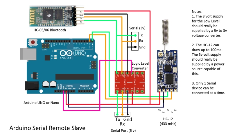
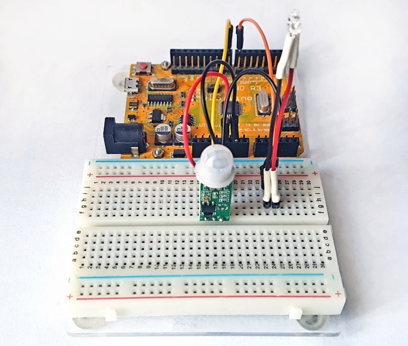
To try them out build two circuits as in the picture above (connections are shown in the sketch) and upload the following sketch to each. (I make no claim to the authorship of this code as its fairly standard Serial Communication code).

/*********************************
Simple demonstration of HC-12 433mHz Radio
Connect Vcc to Arduino 5volts
Connect Gnd to ArduinoGnd
Connect Rx to Arduino pin 3 (Tx)
Connect Tx to Arduino pin 2 (Rx)
Connect SET to Arduino pin 4 (Take LOW to send AT Commands)

To switch HC-12 to AT Mode, take AT PIN LOW
To return to Normal Mode take ATPIN HIGH

*********************************/

#include <SoftwareSerial.h>
#define ATpin 4 // used to switch to AT mode
#define LEDpin 13
SoftwareSerial HC12Serial(2, 3); //RX, TX

void setup() {
Serial.begin(9600);
Serial.setTimeout(20);
pinMode(ATpin, OUTPUT);
digitalWrite(ATpin, HIGH); // normal mode
//digitalWrite(ATpin, LOW); // AT Mode
pinMode(LEDpin, OUTPUT);
digitalWrite(LEDpin, LOW);
HC12Serial.begin(9600);
HC12Serial.setTimeout(20);
}

void loop() {
if(Serial.available() > 0){ // Read sent TO HC-12
String input = Serial.readString();
HC12Serial.println(input);
}
if(HC12Serial.available() > 0){ // send data FROM HC-12
String input = HC12Serial.readString();
Serial.println(input);
}
delay(20);
}

Now open up two Arduino IDE’s, connect one to the first Arduino (say this is a UNO on COM Port 36) and the other IDE to the second Arduino (say this is a Nano on COM Port 37)

Open the Serial Monitors on both IDE’s and in one type something, it will appear in the Serial Monitor of the other IDE, and so on. So thats it! Simple, effective and cheap (and it needs NO library).

Using the Command Mode:

Like a Bluetooth HC06, the HC-12 uses AT Commands to set the Radio up. To switch to AT Mode simply take the SET pin LOW. This can be achieved by un-REMing the line

digitalWrite(ATpin, LOW);

Upload the sketch and the HC-12 will be in Command Mode, switch to the Serial Monitor and type in AT (9600 baud), you should see OK printed out. Try AT+RX to see all the values for the HC-12 parameters.

These are the commands you can use (all commands are in Capitals):

• AT Test command.  Send command “AT” to the module, and the module returns “OK”.

• AT+Bxxxx  Change the serial port baud rate. The baud rate can be set to 1200bps, 2400bps, 4800bps, 9600bps, 19,200bps, 38,400bps, 57,600bps, or 115,200bps. The default value is 9600bps. e.g: To set the serial port baud rate of the module to 19,200bps, send command “AT+B19200” to the module, and the module will return “OK+B19200”. After exiting from command mode, the module will begin to communicate at 19,200bps.

• AT+Cxxx  Change wireless communication channel, selectable from 001 to 127 (for wireless channels exceeding 100, the communication distance cannot be guaranteed). The default value for the wireless channel is 001, with a working frequency of 433.4MHz. The channel stepping is 400KHz, and the working frequency of channel 100 is 473.0MHz. e.g: To set the module to work on channel 21, send command “AT+C021” to the module, and the module will return “OK+C021”. After exiting from command mode, the module will work on channel 21, with a working frequency of 441.4MHz. Note: As the wireless receiving sensitivity of the HC-12 module is relatively high, when the serial port baud rate is greater than 9600bps five adjacent channels should be staggered for use. Even when the serial port baud rate is not greater than 9600bps, over short distances (less than 10m) also five adjacent channels should be staggered for use.

• AT+FUx  Change the serial port transparent transmission mode of the module. Four modes are available, namely FU1, FU2, FU3, and FU4. Only when the serial port speed, channel, and transparent transmission mode of two modules is set to be the same, can normal wireless communications occur. For more details, please see the above section “Wireless Serial Port Transparent Transmission”. e.g: Send command “AT+FU1” to the module, and the module returns “OK+FU1”.

• AT+Px  Set the transmitting power of the module, with x selectable from 1 to 8. The corresponding transmitting power of the module is as shown below: x value 1 2 3 4 5 6 7 8 Transmitting power of module -1 dBm (0.8mW) 2 dBm (1.6mW) 5 dBm (3.2mW) 8 dBm (6.3mW) 11 dBm (12mW) 14 dBm (25mW) 17 dBm (50mW) 20 dBm (100mW) The default value is 8, and the higher the transmitting power, the further the possible wireless communication distance. When the transmitting power level is set to 1, the transmitting power is at the minimum. Generally speaking, every time the transmitting power is reduced by 6dB, the communication distance will be reduced by half. e.g: Send command “AT+P5” to the module, and the module returns “OK+P5”. After exiting from command mode, the transmitting power of the module will be set to 11dBm.

• AT+Ry  Obtain a single parameter from the module, where y is any letter among B, C, F, and P, respectively representing: baud rate, communication channel, serial port transparent transmission mode, and transmitting power. Example 1: Send command “AT+RB” to the module, and if the module returns “OK+B9600” it is confirmed that the serial port baud rate of the module is 9600bps. Example 2: Send command “AT+RC” to the module, and if the module returns “OK+RC001” it is confirmed that the communication channel of the module is 001. Example 3: Send command “AT+RF” to the module, and if the module returns “OK+FU3” it is confirmed that the module is working in serial port transparent transmission mode FU3. Example 4: Send command “AT+RP” to the module, and if the module returns “OK+RP:+20dBm” it is confirmed that the transmitting power of module is set to 20dBm (100mW).

• AT+RX  Obtain all parameters from the module. Returns serial port transparent transmission mode, serial port baud rate, communication channel, and transmitting power in that order. e.g: Send command “AT+RX” to the module, and the module returns “OK+FU3\r\n OK+B9600\r\n OK+C001\r\n OK+RP:+20dBm\r\n”. (“\r\n” means return\newline) • AT+Udps Set data bits (d), parity (p), and stop bits (s) for serial port communication. For parity, N means none, O means odd check, and E means even check. For stop bits, 1 means one stop bit, 2 means two stop bits, and 3 means 1.5 stop bits. e.g: To set the serial port format to eight data bits, odd parity, and one stop bit, send command “AT+U8O1” to the module. The module will return “OK+U8O1”.

• AT+V  Request firmware version information from the module. e.g: Send command “AT+V” to the module, and the module returns “HC-12_V2.3”.

• AT+SLEEP  After receiving this command, the module will enter sleep mode upon exiting from command mode, with a working current of about 22uA. This mode doesn’t allow serial port data transmission. Upon entering command mode again the module will exit from sleep mode automatically. e.g: When wireless data transmission is not needed, to save power send command “AT+SLEEP” to the module, and the module will return “OK+SLEEP”. Upon exit from command mode the working current will drop to about 22uA.

• AT+DEFAULT  Set serial port baud rate and configuration, communication channel, power, and serial port transparent transmission mode back to the factory default values. e.g: Send command “AT+DEFAULT” to the module, and the module returns “OK+DEFAULT”, with the factory default values restored. The factory default serial port baud rate is 9600bps, 8 data bits, no parity, 1 stop bit, communication channel is 001, transmitting power is 20dBm, and serial port transparent transmission mode is FU3.

• AT+UPDATE  Puts the module in the state of waiting for a software update. After receiving this command the module will not respond to any further AT commands until power has been cycled.

(AT Commands from HC-12 Wireless Serial Port Communication Module User Manual version 2.3B)

Controlling a remote Arduino using a PC

The various Arduino Sketches and the controlling PC program can be found on my GitHub page here.

arduino-serial-remote-commander

 This PC program was written using Visual Basic 2010 on a Windows 7 machine, but the program has been tested on a Windows 10 machine, so it should work on most PCs. It does not install anything on the PC and can be run from a USB stick.

Warning – This is a long blog, but it can be summed up simply as 1. set up the Arduino using the Serial Option of your choice and upload the sketch. 2. Plug the Master into a PC running the control program 3. Control the Slave Arduino.

Overview:

The PC program monitors the five Analog Pins and the  Digital Pins D2 to D13 on a remote Arduino. The state of these pins is displayed and updated every 500 ms, the Digital OUTPUT pins can be switched with a button on the PC screen. Communication is via the Serial Port and at the PC end an Arduino is plugged into a USB socket, communication to the Slave Arduino is either by a direct connection, via Bluetooth using an HC05/06 or using an HC-12 433mHz radio. Distance for Bluetooth is about 30m in free air and although the HC-12 is quoted as having a range of 1800m I suspect that somewhere in excess of 300m in free air should be achievable. This project is designed to monitor and control a remote location (using solenoids or relays) and would not be suitable for use in the remote control of models due to the fairly slow update time.

The Slave Unit:

arduino-serial-remote-slave

Upload the Sketch Arduino_serial_Commander_Slave.ino before connecting the pins D0 and D1 (Rx, Tx) to the circuit.

The circuit diagram shows both Bluetooth and HC-12 radio connected, but in practice only one would be used. If the HC-12 is used then the Logic Level Converter can be left out as it is only needed for the HC05/06. The Serial Connection uses the Arduino’s hardware Serial Port leaving pins D2 to D13 free for control. Pin D13 is used to provide a Beacon function and should be left as an OUTPUT, but the other digital pins can be set up as either INPUTS or OUTPUTS by modifying the sketch

// ————– Pin variables
int command;
int pin13;int pin12;int pin11;int pin10;int pin9;int pin8;
int pin7;int pin6;int pin5;int pin4;int pin3;int pin2;
//
// ————– setup digital pins as OUTPUT or INPUT,
// OUTPUT = 0 (Zero), INTPUT = 1 (One)
//
int pin2Direction = 0;
int pin3Direction = 0;
int pin4Direction = 0;
int pin5Direction = 1; // INPUT
int pin6Direction = 0;
int pin7Direction = 1; // INPUT
int pin8Direction = 0;
int pin9Direction = 0;
int pin10Direction = 0;
int pin11Direction = 0;
int pin12Direction = 0;
int pin13Direction = 0;
//

The sketch sets all digital pins as an OUPUT except for D5 and D7, which are set as INPUTS, but this is easy to alter to your requirements. For an INPUT set the pinDirection for the required pin to 1 and for an OUTPUT set it to 0 (zero).

In the Main Loop a timer sends a string to the Master containing the state of all the pins every 500ms. It listens for data from the Master and if any is available reads it

if(Serial.available() > 0){ // get data sent from Master
String input = Serial.readString();
command = input.toInt(); // convert to an integer

the result, command, is a single number that represents the state of all the digital pins displayed on the PC screen. If you imagine this number in hexadecimal format then 0x0800 represents D13 and 0x0001 represents D2. So, if the number received was 0x0801 then pins D13 and D1 would be set HIGH and all the other pins set LOW. If the next command received was 0x0800 then pin D13 would be left HIGH but pin D2 would be set LOW. This method allows all pins to be controlled by using a single number.

That’s it for the main loop, a subroutine sendDatatoMaster() builds a string containing the state of the Analog and Digital pins to send back to the Master, when requested every 500ms. I settled on 500ms after some experiment as it provides the most reliable connection and trying to send the data at a faster rate led to a large number of failures. No checksum is used because any error will be corrected after the next transmission in 500ms. The Slave transmits data without knowing if the Master has received it, however, if the Beacon is switched ON from the PC then the LED attached to D13 will flash every 2 seconds all the time contact is maintained between the Master and the Slave.

The Master Unit:

arduino-serial-remote-master

Upload the sketch Arduino_serial_Commander_Master.ino to this Arduino.

The wiring of the Master unit is almost identical to the Slave unit except that Software Serial is used on pins D2 (Rx) and pin D3 (Tx) and an additional connection from pin D4 to the HC-12 (if used) SET pin. This allows an HC-12 to be put into COMMAND Mode. As with the Slave Unit, only one Serial method at a time can be used so the wiring can be simplified to suit your needs. The Master Arduino is plugged into a USB port on the PC.

This Arduino does nothing much other than to take the Serial output from the PC and send it to the Slave. Any data it receives it sends back to the PC to be decoded and acted on. It does however, look for two special commands that allow an HC-12 radio to be put into Command mode and this is highlighted in bold below

if(Serial.available() > 0){ // Read from serial input (from PC) and send over HC-12
String input = Serial.readString();
//Serial.println(input); // for debugging
if(input.startsWith(“ATEND”)){
digitalWrite(ATpin, HIGH); // exit AT Mode
digitalWrite(LEDpin, LOW);
}
else if(input.startsWith(“ATSEND”)){
digitalWrite(ATpin, LOW); // go into AT Mode
digitalWrite(LEDpin, HIGH);
}
else{
mySerial.println(input);
}
}

 Clicking the AT Command Mode button will allow AT commands to be sent to the HC-12 in the Master Unit (only). Clicking the button again will return to the Normal mode.

Setting up the Serial Mode:

Before starting make sure the program HC12 Commander.exe is running on a PC and the correct Arduino Sketch has been uploaded to each Arduino.

Mode 1 – Hardware Serial Data Mode

This is perhaps the best mode to start with to make sure everything is working.  Plug the Master Arduino into a USB port on the PC and supply power to the Slave Arduino first. Without either a Bluetooth Unit or HC-12 Radio connected to either the Master or the Slave connect the Tx on the Master to the Rx on the Slave, connect the Rx on the Master to the Tx on the Slave. Connect the Gnd pins on both Arduino Boards together.  (Note before switching off the power to either Arduino remove the Serial and Ground connections first).

With the PC program on your monitor click on the Serial Port Radio Button

commander-serial_port_button

Click on the Baud Rate drop down box and select 9600

commander-baud_rate

Then click on the COM Port drop down box, the COM Ports connected will be shown, select the one that matches your Arduino

commander-comm_port

After a few seconds, the Received Data String box will show that the Master has connected to the Slave, the Serial Port symbol will turn blue and the pin states on the Slave will be shown. As the Slave sketch set up D5 and D7 as inputs their buttons are greyed out. If they are not connected they will normally show HIGH, try connecting pin D7 to pin D8, the value will change to LOW. Click on D8 to change it to HIGH and D7 will go HIGH. The pins that are HIGH are shown on the Arduino picture in red, the onboard LED connected to D13 will turn red when D13 is HIGH. As the update occurs only once every 500ms there will be a slight delay.

commander-connected

Click on the Beacon Off button the title changes to Beacon On and after a slight delay, the onboard LED on the Slave will start to flash once every 2 seconds. This will continue until either the Beacon button is pressed again or the Slave loses contact. Other digital pins can be changed while the Beacon is running.

Now disconnect the three Serial wires after a short delay the Digital Pin display will be greyed out and the Received Data Strings box will show that contact has been lost. The Master then tries to link up with the Slave and will keep doing this until contact is made. The Serial Port icon turns black.

commander-lost

The Beacon LED on the Slave will stop flashing but, remain in the state it was in when contact was lost. Reconnect the three serial wires and after a few moments, the Received Data Strings box will show that contact has been made. The Digital Pins display will become active and if the beacon was running before contact was lost the LED on the Slave will start to flash again.

 The Analog pins tend to float if not connected and the values shown will be random, try connecting one of the Analog pins to a Digital pin. If the digital pin is LOW the Analog pin will be 0, if the digital pin is HIGH the output will be 1024.

The Same procedure is used with Bluetooth and with an HC-12 radio with some minor variations.

Mode 2  – HC-12 433mHz Radio mode:

Connect an HC-12 to the Master Arduino and to the Slave Arduino (do not connect the Serial connection used above), Make sure Tx on the HC-12 connects to Rx on the Arduino and Rx on the HC-12 connects to Tx on the Arduino. Connect the Master Arduino to the PC and connect power to the Slave. Separate the two units by a few feet and go through the procedure to connect as shown in Serial Mode above. This time click on the HC-12 Radio Button before setting the Baud Rate at 9600 and the COM Port to your Arduino. The AT Mode now becomes useable and the Data Strings to Send box and associated buttons become enabled.

In the normal mode, the HC-12 mode acts exactly as the Hardware Serial Data Mode, but if you click on the AT Command Mod Off button the title changes to AT Command Mode ON and the HC-12 is put into Command Mode. Type in AT (upper or lower case) and click the SEND button. OK should be displayed in the Received Data Strings box.

commander-at

Try typing AT+RX and press SEND all the settings on the HC-12 will be shown, use the scroll bars to the right of the box to see earlier data.

Click on the AT Command Mode ON button, it will change to AT Command Mode OFF and you will be back in Normal Mode. Please Note that this cannot be used to set up AT mode on an HC05/06 Bluetooth module.

Mode 3 – Bluetooth HC05/06 Mode:

Bluetooth can be used in two ways, either by using the Arduino Master fitted with a Bluetooth module, or not using the Master and using the Bluetooth on the PC or a Bluetooth dongle instead.

Method 1 – using the Master Arduino fitted  with an HC05 or HC06

The HCo6 is a Bluetooth Slave module and the HC05 is a Master/Slave module. Before starting the HC05 should be configured as a Master and it should be confirmed that the two modules will pair. It is beyond the scope of this blog to cover how this is done, but there is plenty of information on the internet. Fit the HC05 to the Master Arduino and the HC06 to the Slave board (although it does not matter which Arduino the HC05 is connected to). Plug the Master into a USB socket on the PC and run the control program. Select the Bluetooth radio button. Apply power to the Slave board and the LED on both Bluetooth boards will flash. After a few seconds, the LEDs on both Bluetooth LEDs will stop flashing and stay ON, showing that they have paired. Select a Baud Rate of 9600 and select the COM Port for the Master Arduino. After a short delay, the two Arduino’s will connect and the Digital pin display will become enabled.

Method 2 – Using the PC’s Bluetooth instead of a Master Arduino.

If the PC has a Bluetooth or you have fitted a Bluetooth Dongle you can dispense with the Master Arduino. You first need to know which port your Bluetooth is connected to. Click on the Bluetooth Icon in the taskbar and click on Show Bluetooth Devices

commander-bt2

If you have already paired the HC05/06 then it will appear

commander-bt1

If not then click on Add a Device, when asked use the password 1234. Once it has installed the drivers (this may take a few minutes) right click on the device (HC-06 in the picture above) and click on properties to show the following menu screen. Click on Services, this shows the port we want to be COM 110

commander-bt3

Now start the PC program with Bluetooth running. Select the Bluetooth Radio Button. Set the baud rate to 9600 and the COM Port to that found (COM 110) and with the slave powered up, Bluetooth should connect in a short while, the LED on the HCo6 going from flashing to steady.

Simple Circuit to test Solid State Relays

solid-state-relay

Solid State Relays can be purchased mounted on boards from one to eight mounted on boards for the Arduino. I purchased a two relay board, like this one here. Currently they cost around two to three times a conventional relay mounted on a PCB. The advantages are that they are smaller, have no moving parts and are silent in operation.

I put together a simple circuit to test a two channel SSR, but it could be expand as required. The relay board  has a Ground Connection and a 5 volt supply pin. Each relay has a trigger pin. The Relay is switched on with a logic HIGH (5 volts).

The circuit I used is shown here:

solid-state-relay-circuit-diagram

And here is the sketch I used:

/***************************************************
*
* Solid State Relay, Simple Test Circuit
*
* Connections:
* DC_ to Arduino 5 volts
* DC- to Arduino Gnd
* CH1 toArduino pin 2
* CH2 to Arduino pin 3
*
* Chris Rouse December 2016
*
***************************************************/
#define CH1pin 2
#define CH2pin 3

void setup() {
Serial.begin(9600);
pinMode(CH1pin, OUTPUT);
pinMode(CH2pin, OUTPUT);
digitalWrite(CH1pin, LOW); // turn CH1 OFF
digitalWrite(CH2pin, LOW); // turn CH2 OFF

}

void loop() {
digitalWrite(CH1pin, HIGH); // turn CH1 ON
digitalWrite(CH2pin, LOW); // turn CH2 OFF
delay(1000);
digitalWrite(CH1pin, LOW); // turn CH1 OFF
digitalWrite(CH2pin, HIGH); // turn CH2 ON
delay(1000);

}

The two relays are simply turned off and on and the LEDs light to show the relays are operational.

Magic Cup Module with Arduino

magic-cup-module

This is rather an odd module, I had seen them, but only purchased one recently. I assume they are designed to sit at the bottom of a cup and the LED lights up when the cup is tilted. There are four connectors marked +, -, S and L on my board. I decided to draw the circuit out to see how it would connect, the circuit diagram is shown below.

magic-cup-diagram

At first sight it seemed a little odd, I connected pin S and L together and connected the + to the Arduino 5 volt pin and the – to the Arduino Gnd pin. Tilt the module and the LED lights, tilt it back and the LED goes off, the LED is lit when the Mercury switch contact is BROKEN. I assume the reason is that the current drawn through the LED does not pass through the Mercury tilt switch. When the Mercury switch is closed the LED is shorted and a small current flows through the resistor and switch to Gnd. When the Mercury Switch is open the current flows through the resistor and LED to Gnd and it lights up.

magic-cup1

This picture shows the mercury bead does not cover both contacts and the switch is OPEN.

magic-cup2

This shows the contacts CLOSED as the Mercury covers both contacts and the LED is OFF.

The circuit does not really need the Arduino and will work happily with juts a 5 volt power supply. However, as both the switch and LED are available individually I wrote a short Sketch that allows the operation to be changed, or used in a much bigger project.

/**************************************************
*
* Magic Cup Demonstration
*
* Chris Rouse December 2016
*
* Connections:
* + or Vcc to Arduino 5 volts
* – to Arduino Gnd
* S (Mercury Tilt Switch) to Arduino pin 8
* L (LED connection) to Arduino pin 7 via a 220R resistor
*
* Note: a 220R resistor must be used in series with the LED or it will be destroyed
*
**************************************************/

#define mercuryTilt 8
#define LED 7
#define onBoardLed 13
boolean state = false;
boolean initialState;

void setup() {
pinMode(mercuryTilt, INPUT);
pinMode(LED,OUTPUT);
pinMode(onBoardLed, OUTPUT);
initialState = digitalRead(mercuryTilt);
digitalWrite(LED, LOW); // start with LED off
}

void loop() {
state = digitalRead(mercuryTilt);
if(state != initialState){
digitalWrite(LED, HIGH); // turn LED ON if switch has been tilted
digitalWrite(onBoardLed, HIGH); // echo output to Arduino’s LED
}
else{
digitalWrite(LED, LOW);
digitalWrite(onBoardLed, LOW);
}
}

The sketch first determines which way up the tilt switch is and makes this the OFF position, when the switch is tilted the LED will be turned ON. to reverse this action change the line

if(state != initialState){

to

if(state == initialState){

The LED will be ON until the switch is tilted

I admit that this circuit could have been built using discreet components, but I purchased two of these modules for less than £1 on eBay, post paid.


Joystick Weather Clock, 15 months on

joystick-weather-clock

The original post for this project can be found here  A link to all the files on GitHub can be found here.

Following a suggestion from Alan Powell I decided to add a Humidity Sensor. The DHT11 is cheap and suited to this project. A lack of variable space meant that I was unable to save the data to the SD Card but as a bonus, the Humidity screen displays the Dew Point. See the end of this blog for more details.

Back in September 2015, I built this Joystick Weather Clock and it has sat on my desk recording pressure and temperature on an SD Card for fifteen months, without missing one hourly record. The data was stored as a CSV file so that it would load into EXCEL or similar spreadsheet program. I decided to see how it was faring after running all that time uninterrupted.

The fact that it was still saving data meant that there had been no stack overflow caused by unused variables filling up available free memory. The DS1307 Real time clock had not done too well, it was now 45 minutes fast, gaining around 38 seconds per week. The OLED display seemed to have lost a number of pixels and in places the display looked a little ragged, the LEDs used to light up under the display were still going strong. The pressure sensor was working perfectly.

So much for the hardware, what about the software? The calendar was perfect, having come through a leap year and the moon phase display was spot on. Data had been recorded exactly as designed and the whole file on the SD Card took up less than 4mb. Over 11,000 hourly temperature and pressure readings had been recorded and I believe this unit could run unattended for several years.

The pressure information was the most interesting, it was possible to follow the remains of a hurricane that hit the UK at the start of January 2016.

pressure-graph

The pressure had remained fairly stable at around 102000 pascals until New Year’s Eve, dropping to below 98000 pascals over four days. The result was high winds and flooding.

I am really pleased with the software side, but I feel that a better Real Time Clock module is needed. To protect the OLED I think some kind of simple Screen Saver is needed and I will add this in the new year sometime. The subroutines to calculate the calendar and moon phase have worked flawlessly and, although the data saved on the SD Card is OK, I think that a VBA routine for EXCEL to extract the Pressure and/or the Temperature data and to place it all in a single column is needed. This will allow a graph to quickly be drawn. Please note that the hourly data builds up throughout the 24 hours and only the data saved at  2300 hours contains all the days’ data.

One final addition would be to use a 5-volt power bank as a backup battery, it can be left plugged into the Arduino and would only be used if the mains power was lost. The software saves the last 48 hours in a temporary file on the SD card, if the power is lost then once power is restored this temporary data is loaded, but if the power is lost for more than one hour the data for the time during power down would be lost.

Adding another Sensor:

The Sketch uses 74% of the available space for variables and at 78% usage the Arduino  IDE starts to complain, so I have tried to keep below this figure. I decided to try to fit a Humidity sensor, following a suggestion from Alan Powell. The DHT11 although slow is quite cheap and as long as you don’t request data too often it should work well. I started by installing the library and the routine to read the Humidity data. That consumed very little precious variable space. I then added a new screen to display the data. Now I had a working Humidity screen that also displayed the Dew Point.

The DHT11 is a slow device that should not be addressed more than once every few seconds. I decided to save the Humidity value and only update it once an hour when data is saved to the SD card. When you display the Humidity screen the value could be up to an hour out of date, but simply press the joystick and the value is updated immediately.

I fitted a ChronoDot board with a DS3231 RTC chip, this is just a simply plug in replacement, I just needed to swap the SDA and SCL lines. No change to Library or Sketch is needed.

Heres to the next 18 months when I can see how well the new RTC performs.

humidity

The new Humidity screen, accessed by moving the Joystick one place left from the Analog Clock Screen. The age of the reading is shown and although this is updated once an hour it can be updated manually at any time by pressing the joystick switch in this screen.

The DHT11 has three pins 5v, OUT and GND. Connect 5v and Gnd to the Arduino and OUT to digital pin 12. While I was fitting the DHT11 I took the opportunity to swap the DS1307 RTC for a (hopefully) more accurate DS3231.

The picture at the top of this post shows the new ChronoDot RTC and DHT11 fitted to the clock.

weather-clock-wiring-diagram

Use this connection diagram in conjunction with the wiring instructions in the sketch. Check the pinouts on your devices before wiring as they may not match those shown above. The OLED will die instantly if not connected correctly.

PIR Detector SR505

pir-sr505

This tiny PIR, movement detector is simple to use and only has three pins, +, – and OUT. it works with 5 volts. Connect the – to the Arduino Gnd, the + to the Arduino 5 volts and the OUT to any digital pin ( I have used pin 8) set as an input. At rest, with no movement the OUT pin is 0 volts (LOW), movement within two to three feet will trigger the SR505 and the OUT pin will rise to 5 volts (HIGH).

There is about a five second ‘latch’ after the movement has stopped, the output staying HIGH, before going LOW again. I have used an LED connected to Arduino pin 7 to show when the SR505 has detected movement, the Arduino’s LED on pin 13 will be ON when there is no movement and OFF during movement and this LED could be used to show the detector is waiting for movement.

The simple sketch is shown below and sits in a loop waiting for the SR505 to trigger. One improvement could be to connect the OUT to an Arduino Interrupt pin this would allow another sketch to run until movement is detected. One application could be to run a display when a visitor is within range etc.

/*******************************************************
* SR505 PIR Detector
*
* by Chris Rouse December 2016
*
* SR505
* + to Arduino 5v
* – to Arduino Gnd
* OUT to Arduino Pin 8
*
* LED connect to pin 7 through a 220R resistor
*
* Once triggered the OUTPUT will stay HIGH for about 5 seconds
*
* Maximum range is about 2 to three feet
*/

#define PIR 8 // the PIR output
#define LED 7 // indicator LED
#define LED13 13 // onboard LED

void setup() {
pinMode(PIR, INPUT);
pinMode(LED, OUTPUT);
digitalWrite(LED, LOW);
pinMode(LED13, OUTPUT);
digitalWrite(LED13, LOW);
}

void loop() {
// the output from the SR505 will go HIGH if movement is detected
if(digitalRead(PIR) == HIGH){
digitalWrite(LED, HIGH);
digitalWrite(LED13, LOW);
}
else{
digitalWrite(LED, LOW);
digitalWrite(LED13, HIGH);
}

} // END

Weather Balloon 2016

Panorama1

This article follows on from the attempt to fly a tethered weather balloon in July 2015, see the blog here.

An opportunity arose early in 2016 to fund another flight of our Helium filled Weather Balloon. This time it was to be used to observe the Isle of Wight Festival. The school I work at is used each year, along with other parkland, for this large music festival. As part of a community involvement by the organisers, the school is given a number of tickets for the event and these are given to students in return for them becoming involved in various projects. This year the Geography Department wanted to look at the environmental impact that the festival has on our community, in particular the problems of litter and the waste generated by the festival.

I was approached to see if the weather balloon could be used to photograph the festival site and the quest for funding started. I had several short meetings with the Geography teacher running this project, but it was not until funding was confirmed in April/May 2016 that planning began in earnest. The price of Helium had increased since 2015, but I managed to track down a supplier who sold us five 0.42 cubic metre balloon gas cans for just over £120. These cans are supposed to fill 50 x 9 inch balloons and from experience will provide about 250 gms of lift.

From our experience the biggest problem was to stop the electronics package from spinning and the original idea was to suspend the package from the balloon, then attach the kite string to the bottom of the package. However, I was concerned about the package surviving the forces involved and went for attaching it as we had done last year (see the blog here). A suggestion was made that we use a wind sock to stop the package from spinning, but as with everything else involved in this project we had nothing to guide us. Eventually we settled on a wind sock about fourteen inches long with the mouth about four inches in diameter (see the photograph below). Four pieces of cord were used to attach the windsock to the end of the package.

We were limited to one of four days, 4th to 7th June as the festival started on the 8th June. The long term weather forecast at first did not look too promising  but by the week before it seemed that Tuesday 5th looked our best bet. It was forecast to be overcast with only a small chance of rain, but more importantly the wind speed was forecast to be about 2km/hr. When the day arrived it was warm and sunny with partial cloud cover, and almost no wind.

It took about an hour to fill the balloon and we used four and a half tins to fill the balloon and provide about 1200 gms of lift. The balloon was then walked to the geography department where the electronics package was started, set to record video then attached to the balloon. The wind sock was fitted to the end of the package and we walked the balloon down to the field alongside the festival.  Weather conditions were perfect and the balloon rose easily to about 100 feet, but the wind sock was too heavy and simply hung below the package, blocking the camera. We brought the balloon back down and stuffed the wind sock onto the top of the package and sent the balloon up several hundred feet.

20160607_142915

showing the windsock mounted in the best position

Lady Luck was certainly on our side because the wind blew the wind sock off the package in such a way that it was supported on the top of the package. At this point it did exactly what it was designed to do and kept the electronics package perfectly still! Over the next two hours we sent the balloon up to various heights and it was not until the end of the day that increasing winds started to move the balloon horizontally. On the last time we brought the balloon down we pulled it down, laying the kite string on the ground, with out winding it onto the reel and this allowed us to measure the height that it reached.

At the end of the day we decided to burst the balloon rather than try to store it overnight, much to the delight of several classes of students who had come out to watch the balloon.

Conclusion:

We achieved all our aims with this flight as far as the balloon was concerned, we were able to control it with ease and confirmed that each container of Helium gave about 220 to 250gms of lift. However,  the electronics package did not perform as expected. I had been testing it for almost a year, running it on battery power for up to eight hours at a time, and it performed perfectly. As I wanted to control it using the LPRS radios I would start the python program using VNC or ServerAuditor on my iPad. However, when the iPad went into screen saver mode it shut down the python program. The solution is to start the python program using  WiFi, then to turn off the router.  VNC or ServerAuditor can be switched off and the python program will continue to run, I have no idea why the python program stops when the header less  control program is shut down, it just does!

The day before the launch, the control of the Raspberry Pi became erratic (it later turned out to be one of the small heat sinks plugged onto the back of the USB sockets that had fallen off and was rolling across the Pi, shorting out connections as it went). As I seal the package with cable ties and wanted to make sure we were filming I set the video to run for 30 minutes. It performed perfectly, it just took 20 minutes of video of the ground as we fitted it to the balloon then walked it to the launch site. For the remaining 10 minutes it filmed the wind sock as it flapped about in front of the camera. As a result we recorded almost no useful video.

The students took plenty of video and still pictures of the event and I am sure the report they write will justify their festival tickets. The students were fascinated by the balloon and followed us wherever we went. Teachers brought their classes out to watch and I am sure the students appreciated the chance to lie on the grass in the sun rather than be stuck in a classroom.

Bursting the Balloon small

bursting the balloon at the end of the day. The white substance is the French Talc in the balloon.

I would like to thank Ann and Toby for their help and suggestions and to Caroline for coming up with a project that allowed us to fly the balloon again.

L9110 Fan Motor Keyes Board

arduino fan2

The Sketch can be downloaded from my GitHub page here and includes the L9110 datasheet.

I came across this somewhat strange board advertised as a Fire Fighter with the claim that the fan was so strong it could be used to put out a flame! With a claim like that I just had to buy one, but I must confess that I have no idea what I will do with it.

The Motor Driver is an L9110 single motor driver that has two inputs INA and INB with two wire out that can drive a small DC motor. It seems to be designed to be used in toys and small robots. INA and INB are driven by logic signals, both inputs set to LOW and the motor is still, with INA HIGH and INB LOW the motor will turn one way and it will turn the other way when INA and INB are reversed.. Two other pins on this board are supplied with  5 volts (Vcc) and Gnd from the Arduino. INA and INB could be supplied with logic signals from any of the digital pins, but the motor speed would not be variable as it would run at full speed in either direction.

PWM can be used to drive the motor at variable speed in either direction and this is what the sketch here does. I found that the lowest stable speed was when the PWM was set to 80, up to the maximum of 255. Below 80 and the speed was a little erratic. I have used a KEYES momentary push button to demonstrate the motor. When the sketch first runs the motor is still. Press the button and the motor rotates, press it again and the motor stops for a brief moment then rotates in the opposite direction. On the third press the motor stops. The short delay when changing direction allows the motor to slow right down first.

The Circuit::l9110 arduino

Circuit diagram

The Sketch::

/*********************************************************
* Fan Driver using L9110 Motor Driver
*
* The L9110 Motor Diver is a simple driver designed for
* toys and robots. It has two inputs INA and INB
* and two outputs to drive a simple DC Motor.
*
* The direction of motor spin can be changed and the speed
* can be controlled using PWM
*
* The device described here is the Keyes Fan Board with
* 4 connections
*
* Connections:
*
* INA to Arduino PIN 5
* INB to Arduino PIN 6
* Vcc to Arduino 5 volts
* GND to Arduino GND
*
* Push Button:
* (the output went LOW on pressing on my unit)
* Gnd to Arduino Gnd
* Vcc to Arduino 5 volts
* S to Adduino PIN 7
*
*******************************************************/
const int INA = 6;
const int INB = 5;
const int pushButton = 7;
const int ledPin = 13; // onboard LED
int action = 0; // 0 = Stop, 1 = Forward, 2 = Reverse

byte speed = 80; // change this to alter speed 0 - 255 although 80 is the minimum for reliable operation

void setup()
{
pinMode(INA,OUTPUT);
pinMode(INB,OUTPUT);
pinMode(pushButton, INPUT);
pinMode(ledPin, OUTPUT); // onboard LED
Serial.begin(9600); // for debug
}

void loop()
{
if (digitalRead(pushButton) == LOW){ // see if button has been pressed
digitalWrite(ledPin, HIGH); // turn on LED
action = action + 1; // increment action
if(action > 2){
action = 0; // keep action in range
}
if (action > 0){
digitalWrite(ledPin, HIGH); // Turn OFF LED if motor stopped
stopFan();
delay(100); // short delay to make direction change easier for motor
}
else digitalWrite(ledPin, LOW); // turn onboard LED OFF
delay(800); // simple switch debounce
}

switch (action){
case 0:
Serial.println("Stop Fan:");
stopFan();
break;

case 1:
Serial.println("Fan Forwards:");
forward();
break;

case 2:
Serial.println("Fan Reverse:");
reverse();
break;
}
}

void reverse(){
analogWrite(INA,0);
analogWrite(INB,speed);
}
void forward(){
analogWrite(INA,speed);
analogWrite(INB,0);
}

void stopFan(){
digitalWrite(INA,LOW);
digitalWrite(INB,LOW);
}

Clap Switch Sound Sensor DIY Kit NeoPixel Ring Display

neopixel_clapswitch

The sketch for this project can be downloaded from my GitHub page here.

This project uses the Clap Switch described in my blog  here and shows how it can be used to step through the display modes in the Adafruit sketch included with the NeoPixel library. I am using a 16 LED NeoPixel ring in this project, if you are using a different number then the number of LEDs needs to be adjusted in the sketch. PIXEL_COUNT is the number of LEDs and PIXEL_PIN is the Arduino pin number connected to DI on the neoPixel ring (in this case Digital pin 5).

Adafruit_NeoPixel strip = Adafruit_NeoPixel(PIXEL_COUNT, PIXEL_PIN, NEO_GRB + NEO_KHZ800);

You need to download and install the Adafruit NeoPixel library from here, I have uploaded my modified version of the Adafruit buttoncycler sketch on my GitHub page here. The original Adafruit sketch used a push switch to change the display, I modified the sketch to use the output from the Clap Switch. With the sketch (clapSwitch_buttoncycler.ino) loaded the NeoPixel display should be OFF. Clap your hands and the LED on the clap switch should go OFF. The NeoPixel ring will start flashing in one of nine patterns, it will continue until you clap again. The ring will stop at the end of the current cycle (which in the case of some of the rainbow patterns may take a few seconds). Clap to start the display running again.

The Sketch::

The sketch is modified from the Adafruit buttoncycler sketch, the code to operate from a push button has been removed and new code to monitor the clap switch has been added. My original code had to be modified slightly as it required two Claps to switch the display ON or OFF. The modified code uses one Clap to start the display and one to stop. The variable trigger is flipped between TRUE and FALSE, with the red LED on the clap switch showing the state (ON = trigger TRUE). The value is checked at the start of the main loop, however, with some of the displays that run for some time, trigger will not be checked until the current display has finished. This will result in a delay before the display is stopped.

The clap switch output turns the on-board LED, on pin 13, ON and OFF to indicate when the variable trigger has been read.

Circuit::

clapswitch_neopixel

Please note that for illustration purposes the NeoPixel ring is shown as being powered by the Arduino. For normal use the NeoPixel ring should be supplied from an external stabilised 5 volt supply.

Clap Switch Sound Sensor DIY Kit

clap switch

This kit is available on eBay for less than £2 and I purchased mine from here. The PCB is of reasonable quality and screen printed with all the component values that make it easy to build this project. Several components need to be connected in one direction, the two electrolytic capacitors easy to align as the negative is shown shaded, the two small diodes have a black band on one end and both are aligned in the same direction. The symbol for a diode is printed on the PCB and the bar on the symbol represents the black band on the component. There are four transistors and they should be inserted on the board so that the flat on the transistor aligns with the flat printed on the board. The microphone position shows a + and a -, but no markings were printed on my microphone. However, the pins are offset and the microphone can only be fitted one way so that it fits inside the printed circle. The last component the needs fitting correctly is the LED, this has one leg longer than the other and, more importantly, a flat on one side. The LED is aligned so that it faces to the edge of the PCB, if it is fitted the wrong way round the completed board will not work.

All the remaining components can be fitted either way round, resistors need to have their their leads bent close to the body. There are two values of capacitor, 0.1mfd and 0.01mfd (marked as 104 and 103 respectively), fit the 103 first, then fit 104 capacitors to avoid fitting the 103 in the wrong place. The power socket should obviously be fitted with the open end facing the edge of the board. I soldered a two pin plug to the supplied power lead so that it could be plugged into the Arduino 5volt and Gnd.

Once everything is soldered you will probably find a small printed rectangle alongside the LED with two holes, mine was printed with Link. At first I thought I had a missing component or a small wire link was required, but checking the copper side of the PCB showed one of the solder pads was connected to the 5volt track and the other solder pad was on a copper track alongside the 5volt track. I suspected that this may be the output from the Clap Switch and decided to fit a two pin male header. However, the hole spacing was not exactly 0.1 inches and I had to very carefully enlarge the holes. Be very careful not to destroy the solder pads or push the off the board if you do this! The alternative is to simply solder two leads into these holes, it’s up to you.

The board is very compact and the solder pads vey close together so be careful not to short pads. I use a stiff brush and alcohol to clean all the flux etc from the board after soldering. Use a magnifying glass to check for dry joints and shorts. Once you are happy all is well you can connect to a 5 volt supply or use the 5volt and Gnd pins on an Arduino. The LED will light up (it did on mine, but this may be random). Clap your hands about 1 foot from the microphone and the LED will change state. Clap again and it will change state again.

I suspect, although I have not checked, that the circuit is a microphone pre amplifier with its output fed into a bistable flip flop similar to this one


Which is why the output remains in one state and need another trigger to switch to the other state. I used a multimeter connected to the two pins I had soldered alongside the LED, when the LED was lit it showed about 4.8volts and when the LED was off it showed just under 1 volt. The pin closest to the edge of the board is always 5 volts, so I ignored that on, the other pin will be equivalent to HIGH when the LED is not lit and LOW when lit.

I use the term Clap Switch Output pin to identify the pin circled in red below. The pin above this is connected to the 5volt PCB track and can be ignored. It is important that the Gnd of the Clap switch is connected to the Arduino Gnd, but if it is powered from the Arduino this will happen automatically.

I did try using the output from the Clap Switch to trigger an interrupt on the Arduino pin 2 and this worked well in a quiet room, however the results were erratic with background noise. There is no rush to read the state of the switch, simply read the state at a convenient point in your sketch. The sketch below shows how this can be done, it reads the voltage on pin A0 and sets the variable trigger to False if it is above 2 volts and True if it is below 2 volts. The onboard LED on pin 13 is the lit if  trigger is True.

/***********************************************************
Clap Switch Simple Control
by
Chris Rouse
May 2016

Connections:

Vcc to Arduino 5 volts
Gnd to Arduino Gnd
Output to Arduino Analog pin 0

***********************************************************/
const byte ledPin = 13;
boolean trigger = false; // used to show clap output ON
int triggerLevel = 100; // change this if background noise is high
int outputReading; // voltage output from Clap Switch

/*********************************************************/
void setup() {
Serial.begin(9600);
pinMode(ledPin, OUTPUT);
digitalWrite(ledPin, LOW); // turn LED OFF
}
/*********************************************************/
void loop() {
checkSwitch(); // see if the switch has been triggered
if(trigger){
digitalWrite(ledPin, HIGH);
}
else{
digitalWrite(ledPin, LOW);
}
//

// put the rest of your program here

//
}
/*********************************************************/
void checkSwitch() {
outputReading = analogRead(14);
if(outputReading > triggerLevel){
trigger = false;
}
else{
trigger = true;
}
}
/*********************************************************/