Weather Balloon 3 – Testing wifi over a distance

The plan is to use BerryCam to take pictures of groups of people and these pictures would be available to anyone who has the IP address of the router. I suspect that in order for people to be recognised the height of the balloon would not need to be too great. Taking pictures of the surrounding countryside would then be accomplished under programme control. At a rough guess something around 100 feet could be about right, although that’s just a guess.

So I need to be able to use WiFi to at least 100 feet although more range would be good. There is a long straight corridor where I work that is 30m long, just under the 100 feet I want. There is access to mains sockets at each end so I set up the router at one end and the Raspberry Pi with camera at the other.

On the day the router will on the ground with the Raspberry Pi in the air, so to mimic this I stood alongside the router. Using my iPad I was easily able to control the Pi using the iPad and take pictures on the Pi over 30m away. Looking at the WiFi signal strength I suspect the distance that the iPad will be able to control picture taking will be well over 100ft, but it will not be possible to identify people at this range.

The picture below shows the view down the 30 m corridor with me standing on the right, just visible.

2015/01/img_1616.jpg

Time lapse photography on the Raspberry Pi

This is part of my Weather Balloon project.

There are a lot of tutorials on the Internet showing how this can be done, but I spent some time trying to get it to work. The following procedure worked for me and may be of use to others.

Start the LX Terminal to enter the following:

Step 1 – make a new folder where all the files and images will be kept.

mkdir Timelapse

cd /home/pi/Timelapse


This creates a new folder then navigates to that folder.

Step 2 – write code that will take a picture

Create a new file called timelapse.sh

nano timelapse.sh

Then enter the following code

#! /bin/bash
DATE =$date("%d-%m-%Y_%T")
raspistill -o /home/pi/Timelapse/$DATE.jpg

Save and exit by clicking on Ctrl x

To check this works enter

sh timelapse.sh

The LED on the camera board should light and a picture should be taken and saved to the Timelapse folder with the date and time as a file name.

If all is well then you need to write the code that will take pictures at regular intervals. Crontab is used and it is started as follows.

Step 3 – The Crontab code.

crontab -e

This starts the editor, scroll down to the bottom of the code and enter the following code

*/1 * * * * /home/pi/Timelapse/timelapse.sh

This is where I went wrong, no one said that there has to be a space after the */1 and between each of the * characters and a space before the command address. Without those spaces it will not work, and I admit that the code on the Internet had those spaces but they were impossible to see on my iPad.

Save and exit and if all is well the camera will start taking pictures at a 1 minute interval. This can easily be changed, for example */15 would take images at a 15 minute interval.

If an error message is shown when you exit from crontab go back and check the code.

Controlling Cron.
sudo /etc/init.d/cron stop
sudo /etc/init.d/cron start
sudo /etc/init.d/cron restart

All the images will be in the Timelapse folder and a programme like AVIdemux can be used to stitch them into a movie.

OLED displays do not have reverse polarity protection!

As if this weekend was not bad enough after I fried my Raspberry Pi, I managed to destroy a brand new OLED display. I mistakenly reversed to power leads and that was the end of that. In future I will double check all the connections, I just have to hope that the old saying of things come in threes is not true.

Disaster with the Raspberry Pi camera.

I was running a few tests with the Pi camera when I dropped it, now the cable is just the right length so that the back of the camera hits the GPIO pins. With that the camera would no longer work and every time I tried to connect it I got the following error report:

received unexpected camera control callback event 0x4f525245

2015/01/img_1599.png

When I Googled this error I found it was a fairly common problem and that it meant the camera was dead. I tried a new camera but that also gave the same error. At this point I began to suspect I had corrupted the operating system, so I built a new Raspian SD card, but the camera still would not work.

When I tried both cameras on another Raspberry Pi they both worked, so I had not fried the camera but the Raspberry Pi instead. The camera is cheaper than the Pi so in some ways I would have preferred it to have been the camera that had died. At least the Pi retains some functionality, it just will not operate a camera.

The moral of this tale is that it is necessary to take the greatest care when handling that tiny camera and that sometimes the Internet may not have the right answer.

Weather Balloon 2. Connecting the Pi to an iPad

Most of the software I have had running before except for the radios. The first task was to try and link the Raspberry Pi to my iPad so that I could control the picture taking from the ground. Easy to do when everything was connected to my WiFi at home but could be a problem in the middle of a field.

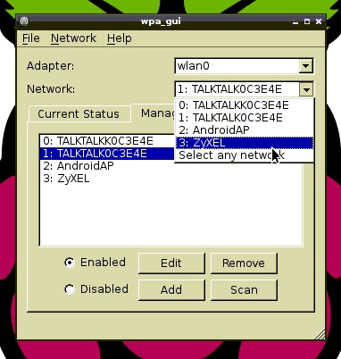
I had an unused ZyXEL router which could be powered from a 12 volt battery and I used the following procedure to connect it. Ensure the router is reset to factory defaults and no password is set. First I connected the iPad using VNC to the WiFi in the normal way, turned on the router and waited for a few minutes to make sure that everything had settled down. I opened the wpa_gui on the Pi and clicked on the Scan button.

2015/01/img_1596.png

After a few minutes it found the ZyXEL router, click on the drop down list in the network box, then double click on the router. Everything will now stop because the VNC program has lost contact with the Pi.

2015/01/img_1597.png

Close down VNC and go to settings on the iPad in WiFi settings select your router and once it’s connected restart VNC and the Raspberry Pi desktop should appear. Of course it will not be possible to access the Internet unless the router is connected to the Internet.

Weather Ballon 1.

The first of what should be a series that will end in mid June 2015. I have just purchased a 2.5 metre weather balloon and six canisters of Helium to fill it with. The plan is to fly the balloon over the Isle of Wight Festival site in mid June. A Raspberry Pi with camera will be used to take pictures and video while an Arduino will be used for control and to collect sensor data. I hope to use radio links and WiFi to control the picture and video taking.

I only have the ideas at the moment and the means of achieving them remain a mystery. The available hardware at the start of the project are a Raspberry Pi Model B, several Arduino boards and a variety of sensors including GPS. EasyRadio USB radios will be used for control although I also have a pair of NRF24l01 radios that could be used. A Pi camera and a 7.2 volt LiPo battery complete the hardware at the start.

I have no idea how much Helium is going to be needed or what the problems are going to be trying to inflate it, but I expect I will discover that when it come time to fill the balloon. The payload is another unknown, one Internet source quoted at least 2kg but I will believe that when I see it. A bare minimum of hardware – Raspberry Pi, camera and LiPo battery is just over 100 gms, so there should be no problems.

Arduino and the BMP085 environmental pressure and temperature sensor

2015/01/img_1582.jpg

The BMP085 I have is an I2C device with seven pins, but only four, Vcc, Gnd, SCA and SCL are used (pins are in that order). I found a number of sketches but feel that the best was the one on the Adafruit site,

I made one small change, I wanted to plug the sensor straight into the Arduino, so I made A2 and A3 power pins. If you want to do the same insert the following code into the sketch at the start of the void setup() loop


pinMode(17, OUTPUT);
digitalWrite(17, HIGH); // make this pin 5 volts
pinMode(16, OUTPUT);
digitalWrite(16, LOW); // make this pin Gnd


Just a word of warning if you do this, make sure your board needs 5 volts not 3.3 volts to power it and also make sure your pinout matches mine!

The altitude is only correct if you know exactly what the pressure is at sea level as this sketch assumes it is 101500 pascals. Height is calculated by knowing the difference in pressure between your location and sea level.

Arduino comparable board with CH340G USB chip.

/home/wpcom/public_html/wp-content/blogs.dir/10d/72092500/files/2015/01/img_1577.png

A number of Chinese built Arduino boards fitted with a cheaper USB chip, the CH340G are appearing on eBay. I purchased one recently for £2.83 post paid and it arrived from China in less than two weeks. So what are they like? The USB chip needs a driver, but I had no problem finding the driver on the Internet. Installing the driver was easy, just running the provided exe file.

The board looks like a UNO to the Arduino IDE, so once the driver is installed just select the right port and connect it as a UNO. So how does it differ? To me this board is an improvement on the official board, there are two extra analog pins, the USB connector is a standard mobile phone type USB connector. This removes the problem of shields shorting out on the standard USB connector. There is a group of 2 x 4 pins where Tx and Rx as well as SDA and SCL are brought out (together with 5v and Gnd). The board I purchased also had a strip of pins to solder onto the board to take advantage of these additional features. A useful feature is the ability to solder male pins alongside the usual female pins.

In my view this board improves on the official board and at this price it’s unbeatable.

Arduino LDR shield


This LDR shield is often available on eBay for about £1 with free postage. It has 4 pins, 5volts, GND, Digital Output and Analog Output. There are two leds, one for power and the other shows the state of the digital output. There is a potentiometer that is used to set the trip level, this output goes LOW when the light level is greater than the trip level. The output from the analog output decreases as the light level increases and is about 1000 mv in darkness to about 50 mv in bright light. 

 The following simple sketch displays the outputs on the Serial Monitor and there is a delay that reduces the output to a reasonable rate. The four pins are plugged into the Analog pins A0 to A3, power is supplied from pins A2 and A3, A0 is set as an Analog input and A1 is set as a Digital input.

Before using this sketch make sure your board pin outs match the board shown in the picture above.   

/***********************************************************

LDR board

this sketch reads the Analog and Digital outputs
and displays them on the serial monitor.
The digital output could be used to activate an alarm etc

Connections:

AO to Arduini A0 - the analog output
DO to Arduino A1 - the digital output
GND to Arduino A2 - supplies gnd
Vcc to Arduino A3 - supplies 5 volts

The output of the LDR falls from about 1000mv in darkness to about 50 mv in bright light
The digital output goes LOW lighting an LED on the LDR board
when the light is brighter than the set trip level.
Use the potentiometer to adjust the trip level.

***********************************************************/

int analog = 14; // Arduino A0
int digital = 15; // Arduino A1
int gnd = 16; // supplies 0 volts
int power = 17; // supplies 5 volts

void setup() {
Serial.begin(9600); // start Serial Monitor
pinMode(13, OUTPUT);
digitalWrite(13,LOW); // turn OFF the LED on Arduino pin 13
pinMode(digital, INPUT); // this pin reads the digital output, either HIGH or LOW
pinMode(power, OUTPUT);
digitalWrite(power,HIGH);// this pin will supply 5 volts
pinMode(gnd, OUTPUT);
digitalWrite(gnd,LOW); // this pin will supply the GND to the board
}

void loop() {
// print the analog output in milli volts
Serial.print("Analog level = ");
Serial.print(analogRead(analog));
Serial.println(" mv"); // milli volts
// print the digital Output LOW = alarm tripped
Serial.print("Digital level =");
if (digitalRead(digital) == HIGH){
Serial.println(" HIGH");
}
else{
Serial.println(" LOW");
}
delay (1000); // this just makes it easier to read the serial output.

}

Arduino Nano Extension Prototype Shield

nano breakout board

My usual route that I follow when working on a project is to use an Arduino UNO, then if the project is going to be mounted in a box or case I use an Arduino Nano. These tiny Arduino’s are just about identical to a UNO by are not much bigger than a postage stamp and can be had on ebay for less than £3.

The other week I discovered this ‘breakout’ board that cost just over £3 from ebay and sent off for one. It arrived today and I am so impressed with it. There are a series of plated through holes on the edge that I intend to solder female sockets to and that will allow me to connect both female and male connections to.

I know that the footprint is now back up to the size of a UNO, but it will be so much easier to connect sensors to, without using a sensor shield, or worse having to use a male/male connector to connect a female/female connector to the Arduino. I know that male/female connectors exist, I just dont have too many of them.

Each pin on the arduino has a GND and +5volt pin, there are plenty of 3.3v, 5volt and GND pins. Tx, Rx, SDA and SDL are also broken out to pins. I can see this little board becoming my main development workhorse.