
The various Arduino Sketches and the controlling PC program can be found on my GitHub page here.

This PC program was written using Visual Basic 2010 on a Windows 7 machine, but the program has been tested on a Windows 10 machine, so it should work on most PCs. It does not install anything on the PC and can be run from a USB stick.
Warning – This is a long blog, but it can be summed up simply as 1. set up the Arduino using the Serial Option of your choice and upload the sketch. 2. Plug the Master into a PC running the control program 3. Control the Slave Arduino.
Overview:
The PC program monitors the five Analog Pins and the Digital Pins D2 to D13 on a remote Arduino. The state of these pins is displayed and updated every 500 ms, the Digital OUTPUT pins can be switched with a button on the PC screen. Communication is via the Serial Port and at the PC end an Arduino is plugged into a USB socket, communication to the Slave Arduino is either by a direct connection, via Bluetooth using an HC05/06 or using an HC-12 433mHz radio. Distance for Bluetooth is about 30m in free air and although the HC-12 is quoted as having a range of 1800m I suspect that somewhere in excess of 300m in free air should be achievable. This project is designed to monitor and control a remote location (using solenoids or relays) and would not be suitable for use in the remote control of models due to the fairly slow update time.
The Slave Unit:
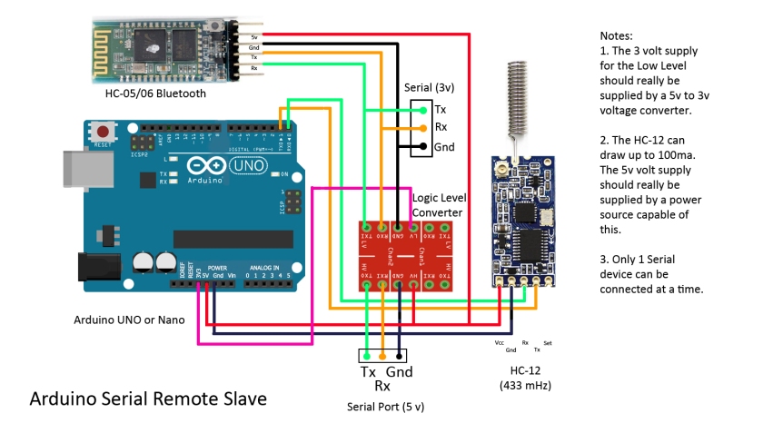
Upload the Sketch Arduino_serial_Commander_Slave.ino before connecting the pins D0 and D1 (Rx, Tx) to the circuit.
The circuit diagram shows both Bluetooth and HC-12 radio connected, but in practice only one would be used. If the HC-12 is used then the Logic Level Converter can be left out as it is only needed for the HC05/06. The Serial Connection uses the Arduino’s hardware Serial Port leaving pins D2 to D13 free for control. Pin D13 is used to provide a Beacon function and should be left as an OUTPUT, but the other digital pins can be set up as either INPUTS or OUTPUTS by modifying the sketch
// ————– Pin variables
int command;
int pin13;int pin12;int pin11;int pin10;int pin9;int pin8;
int pin7;int pin6;int pin5;int pin4;int pin3;int pin2;
//
// ————– setup digital pins as OUTPUT or INPUT,
// OUTPUT = 0 (Zero), INTPUT = 1 (One)
//
int pin2Direction = 0;
int pin3Direction = 0;
int pin4Direction = 0;
int pin5Direction = 1; // INPUT
int pin6Direction = 0;
int pin7Direction = 1; // INPUT
int pin8Direction = 0;
int pin9Direction = 0;
int pin10Direction = 0;
int pin11Direction = 0;
int pin12Direction = 0;
int pin13Direction = 0;
//
The sketch sets all digital pins as an OUPUT except for D5 and D7, which are set as INPUTS, but this is easy to alter to your requirements. For an INPUT set the pinDirection for the required pin to 1 and for an OUTPUT set it to 0 (zero).
In the Main Loop a timer sends a string to the Master containing the state of all the pins every 500ms. It listens for data from the Master and if any is available reads it
if(Serial.available() > 0){ // get data sent from Master
String input = Serial.readString();
command = input.toInt(); // convert to an integer
the result, command, is a single number that represents the state of all the digital pins displayed on the PC screen. If you imagine this number in hexadecimal format then 0x0800 represents D13 and 0x0001 represents D2. So, if the number received was 0x0801 then pins D13 and D1 would be set HIGH and all the other pins set LOW. If the next command received was 0x0800 then pin D13 would be left HIGH but pin D2 would be set LOW. This method allows all pins to be controlled by using a single number.
That’s it for the main loop, a subroutine sendDatatoMaster() builds a string containing the state of the Analog and Digital pins to send back to the Master, when requested every 500ms. I settled on 500ms after some experiment as it provides the most reliable connection and trying to send the data at a faster rate led to a large number of failures. No checksum is used because any error will be corrected after the next transmission in 500ms. The Slave transmits data without knowing if the Master has received it, however, if the Beacon is switched ON from the PC then the LED attached to D13 will flash every 2 seconds all the time contact is maintained between the Master and the Slave.
The Master Unit:

Upload the sketch Arduino_serial_Commander_Master.ino to this Arduino.
The wiring of the Master unit is almost identical to the Slave unit except that Software Serial is used on pins D2 (Rx) and pin D3 (Tx) and an additional connection from pin D4 to the HC-12 (if used) SET pin. This allows an HC-12 to be put into COMMAND Mode. As with the Slave Unit, only one Serial method at a time can be used so the wiring can be simplified to suit your needs. The Master Arduino is plugged into a USB port on the PC.
This Arduino does nothing much other than to take the Serial output from the PC and send it to the Slave. Any data it receives it sends back to the PC to be decoded and acted on. It does however, look for two special commands that allow an HC-12 radio to be put into Command mode and this is highlighted in bold below
if(Serial.available() > 0){ // Read from serial input (from PC) and send over HC-12
String input = Serial.readString();
//Serial.println(input); // for debugging
if(input.startsWith(“ATEND”)){
digitalWrite(ATpin, HIGH); // exit AT Mode
digitalWrite(LEDpin, LOW);
}
else if(input.startsWith(“ATSEND”)){
digitalWrite(ATpin, LOW); // go into AT Mode
digitalWrite(LEDpin, HIGH);
}
else{
mySerial.println(input);
}
}
Clicking the AT Command Mode button will allow AT commands to be sent to the HC-12 in the Master Unit (only). Clicking the button again will return to the Normal mode.
Setting up the Serial Mode:
Before starting make sure the program HC12 Commander.exe is running on a PC and the correct Arduino Sketch has been uploaded to each Arduino.
Mode 1 – Hardware Serial Data Mode
This is perhaps the best mode to start with to make sure everything is working. Plug the Master Arduino into a USB port on the PC and supply power to the Slave Arduino first. Without either a Bluetooth Unit or HC-12 Radio connected to either the Master or the Slave connect the Tx on the Master to the Rx on the Slave, connect the Rx on the Master to the Tx on the Slave. Connect the Gnd pins on both Arduino Boards together. (Note before switching off the power to either Arduino remove the Serial and Ground connections first).
With the PC program on your monitor click on the Serial Port Radio Button

Click on the Baud Rate drop down box and select 9600

Then click on the COM Port drop down box, the COM Ports connected will be shown, select the one that matches your Arduino

After a few seconds, the Received Data String box will show that the Master has connected to the Slave, the Serial Port symbol will turn blue and the pin states on the Slave will be shown. As the Slave sketch set up D5 and D7 as inputs their buttons are greyed out. If they are not connected they will normally show HIGH, try connecting pin D7 to pin D8, the value will change to LOW. Click on D8 to change it to HIGH and D7 will go HIGH. The pins that are HIGH are shown on the Arduino picture in red, the onboard LED connected to D13 will turn red when D13 is HIGH. As the update occurs only once every 500ms there will be a slight delay.

Click on the Beacon Off button the title changes to Beacon On and after a slight delay, the onboard LED on the Slave will start to flash once every 2 seconds. This will continue until either the Beacon button is pressed again or the Slave loses contact. Other digital pins can be changed while the Beacon is running.
Now disconnect the three Serial wires after a short delay the Digital Pin display will be greyed out and the Received Data Strings box will show that contact has been lost. The Master then tries to link up with the Slave and will keep doing this until contact is made. The Serial Port icon turns black.

The Beacon LED on the Slave will stop flashing but, remain in the state it was in when contact was lost. Reconnect the three serial wires and after a few moments, the Received Data Strings box will show that contact has been made. The Digital Pins display will become active and if the beacon was running before contact was lost the LED on the Slave will start to flash again.
The Analog pins tend to float if not connected and the values shown will be random, try connecting one of the Analog pins to a Digital pin. If the digital pin is LOW the Analog pin will be 0, if the digital pin is HIGH the output will be 1024.
The Same procedure is used with Bluetooth and with an HC-12 radio with some minor variations.
Mode 2 – HC-12 433mHz Radio mode:
Connect an HC-12 to the Master Arduino and to the Slave Arduino (do not connect the Serial connection used above), Make sure Tx on the HC-12 connects to Rx on the Arduino and Rx on the HC-12 connects to Tx on the Arduino. Connect the Master Arduino to the PC and connect power to the Slave. Separate the two units by a few feet and go through the procedure to connect as shown in Serial Mode above. This time click on the HC-12 Radio Button before setting the Baud Rate at 9600 and the COM Port to your Arduino. The AT Mode now becomes useable and the Data Strings to Send box and associated buttons become enabled.
In the normal mode, the HC-12 mode acts exactly as the Hardware Serial Data Mode, but if you click on the AT Command Mod Off button the title changes to AT Command Mode ON and the HC-12 is put into Command Mode. Type in AT (upper or lower case) and click the SEND button. OK should be displayed in the Received Data Strings box.

Try typing AT+RX and press SEND all the settings on the HC-12 will be shown, use the scroll bars to the right of the box to see earlier data.
Click on the AT Command Mode ON button, it will change to AT Command Mode OFF and you will be back in Normal Mode. Please Note that this cannot be used to set up AT mode on an HC05/06 Bluetooth module.
Mode 3 – Bluetooth HC05/06 Mode:
Bluetooth can be used in two ways, either by using the Arduino Master fitted with a Bluetooth module, or not using the Master and using the Bluetooth on the PC or a Bluetooth dongle instead.
Method 1 – using the Master Arduino fitted with an HC05 or HC06
The HCo6 is a Bluetooth Slave module and the HC05 is a Master/Slave module. Before starting the HC05 should be configured as a Master and it should be confirmed that the two modules will pair. It is beyond the scope of this blog to cover how this is done, but there is plenty of information on the internet. Fit the HC05 to the Master Arduino and the HC06 to the Slave board (although it does not matter which Arduino the HC05 is connected to). Plug the Master into a USB socket on the PC and run the control program. Select the Bluetooth radio button. Apply power to the Slave board and the LED on both Bluetooth boards will flash. After a few seconds, the LEDs on both Bluetooth LEDs will stop flashing and stay ON, showing that they have paired. Select a Baud Rate of 9600 and select the COM Port for the Master Arduino. After a short delay, the two Arduino’s will connect and the Digital pin display will become enabled.
Method 2 – Using the PC’s Bluetooth instead of a Master Arduino.
If the PC has a Bluetooth or you have fitted a Bluetooth Dongle you can dispense with the Master Arduino. You first need to know which port your Bluetooth is connected to. Click on the Bluetooth Icon in the taskbar and click on Show Bluetooth Devices

If you have already paired the HC05/06 then it will appear
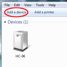
If not then click on Add a Device, when asked use the password 1234. Once it has installed the drivers (this may take a few minutes) right click on the device (HC-06 in the picture above) and click on properties to show the following menu screen. Click on Services, this shows the port we want to be COM 110

Now start the PC program with Bluetooth running. Select the Bluetooth Radio Button. Set the baud rate to 9600 and the COM Port to that found (COM 110) and with the slave powered up, Bluetooth should connect in a short while, the LED on the HCo6 going from flashing to steady.
