
The code, graphics and sound files can be downloaded from my GitHub page here.
I was in an old fashioned Penny Amusement Arcade recently and one of the machines caught my attention. Most of the games were original 1940’s and 1959’s machines modified to take modern coins, but this one machine looked as though it had been built recently. It was housed in a large polished wooden case about five feet high by about eighteen inches wide. It had a two line by forty character LCD display and a large number of discrete LEDs. A voice spoke the phrases displayed on the display.

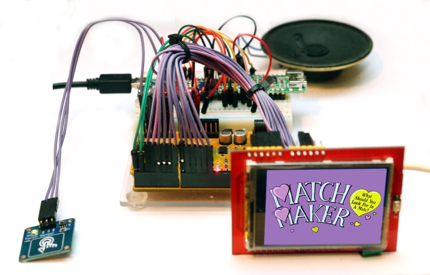
Showing the original machine on the left and a selection of screens from this project
This was a machine designed to find your perfect partner in life! I put my coin into the slot and was told to place my fingers on the sensor. After a few more displayed and spoken phrases the main display came to life, this consisted of six vertical rows of ten LEDs. These represented personality, brain, looks, shape, wealth and height. Each column was lit to a random height to represent the characteristics of your perfect match.
This seemed like a perfect project for an Arduino and colour TFT display and I took some pictures of the machine to remind me of what it did when I got home. I spent several evenings designing the screens for the display in Photoshop. The display is 320×240 pixels and I decided that a landscape format would be the best to use. From previous experiments with the display I knew that a good way to use graphics was to load a full size graphic then to load smaller graphics on top.
The first problem I encountered was that the TFT display used almost all the Arduino pins, except 0, 1 and A5, and I was unable to get it to work with a Mega. The recommendation for using this screen with an Arduino Mega is to modify the library to use software SPI , but it just would not work. I needed to add a touch switch and the WTD588D so it was obvious that something else was needed. Software interrupt would allow the remaining pin, A5, to be used leaving pins 0 and pin 1.
A second Arduino could be used to control the voice chip through commands sent over the serial pins (0 and 1). The final version used two Arduino Nano boards and the WTD588D voice board. The sketch used the Adafruit library for the ILI9341 and part of an example sketch, that loaded BMP image files. This produced a large volume of debug data sent out over the Serial port, very useful for keeping an eye on what was going on, but produced chaos when fed into the Arduino Nano controlling the voice chip. The answer was fairly simple, voice commands were prefixed with a # character. This character does not appear in any of the debug data output, the Nano controlling the voice chip reads all the data coming into the Serial port and just ignores everything until it finds the # character. Data that follows this control character is treated as a voice command by the WTD588D
The circuit:
All three boards fitted onto a piece of solderless board, with the TFT display wired onto the solderless board. The parts required are:
- Arduino Nano x 2 see eBay
- WTD588D -U32M voice board see eBay
- Single capacitance touch switch see eBay
- Breadboard PSU (optional) see eBay
- Breadboard 830 points see eBay
- Jumper wires (male to male and female to male) see eBay
The best thing to do is to upload the programs to each of the three boards before mounting them on the breadboard, all three are fitted with a mini USB socket. (Check your breadboard, the power rails running across the top and bottom may have a break and will require a jumper wire to connect them).
The code is all available on my GitHub page and has the WTD588D project files and the WAV files needed, as well as the two sketches. Arduino_Arcade_Main.ino contains the main code. This needs several libraries – the library for the ILI9341 TFT display shield can be downloaded from the Adafruit site here and the graphics library Adafruit_GFX can be downloaded from here. The software interrupt library called PinChangeInt can be downloaded from here ( I found that SoftwareSerial would not work with this library). For the WTD588D driver Arduino Nano the sketch is Arduino_Arcade_Voice.ino, the library, and instructions for uploading the sound files to the WTD588D can be found on my blog here.

The Gnd pins on all the modules must be connected together. The Arduino controlling the Speech module supplies the 5 volts for it. The main Arduino supplies 5 volts for the touch switch and the display. Originally I powered all modules from a single stabilised 5 volt supply, connecting it to the Arduino’s 5 volt output. A number of articles seemed to show that it was possible, but I eventually killed one of the Arduino’s so went for the option of supplying power to the two Arduino’s through their USB connectors.
The software:
The folder of graphics files should be transferred to an SD Card (the bmp files must be in the root of the SD Card, don’t load a folder to the SD Card). The voice project should be uploaded to the WTD588D as described above. The Arduino that is used to control the WTD588D should have the sketch Arduino_Arcade_Voice.ino uploaded. The main Arduino that controls the TTF Screen should have the sketch Arduino_Arcade_Main.ino uploaded. Upload all the code before wiring the project up. Connect a speaker to pins 9 and 10 of the WTD588D and apply power to both Arduino’s through the USB port, after a short delay the screen should display the opening graphics and speak the associated phrases. The introduction will loop continuously until the touch switch is touched. In the Arcade machine, this serves to attract customers. Once touched the next part of the programme will start providing the random results.
