

See how this project was doing after running non stop for fifteen months here
This project has been updated and now saves data to an SD card. The Git Hub code has been updated. I discovered a problem with the sketch that would give an incorrect February calendar on some years, this problem has been fixed.
Code for this project can be downloaded from my Git Hub page here
If the SD Card is removed to read data while the clock is running, and then returned, the sketch will not be able to read the SD card. Press the Arduino Reset button to restart the sketch and reconnect the Card, the backup data will be uploaded to restore the data on the clock and data will be written to the card.
I wanted to try to build something that used a joystick for control and decided to build a clock with a number of different screens. These screens would be changed using the joystick and the natural choice for display was my small 128×64 OLED. After several weeks of trials I have come up with a clock that has the following specification. All screens are modified in some way, to display additional information, when the joystick button is pressed.
Operation::
Once the circuit is built the code should be uploaded, although an SD card is optional using one will allow data to be restored after a power failure. The card should be formatted with a program like SDFormatter. When the sketch starts it will beep once, if the SD Card is recognised there will be a second beep. If the two files data.csv and backup.dat are not found these will be written to the card. If the backup file is found there will be a third beep as it is loaded. The small LED attached to pin 12 will flash briefly each time the backup is saved or loaded. The data.csv file adds data each hour and can be read by a spreadsheet program like Excel. The backup.dat file is overwritten each hour and contains up to three days data which is uploaded to the clock after a power failure. After the SD Card has been checked a splash screen is shown followed by the Analog Clock. Scroll through the screens by moving the joystick left or right.
The Display Screens::

Screen 1. An analog clock with second hand. The alarm can be set/unset using joystick switch.

Screen 2. A digital clock.Time is displayed in hrs/mins with a flashing colon for seconds. The alarm can be set/unset using joystick switch.

Screen 3. This page is used to set the alarm time. Joystick Y pot is used to set time. The joystick switch allows both minutes and hours to be set. The underline shows which is being altered.

Screen 4. An event timer. Counts up to A maximum of 99 minutes (it will then stop), it is started and stopped with joystick switch. This timer will continue to count when another screen is selected, to stop the counter return to this screen and press the joystick switch. A single beep is sounded every 10 minutes and three times when the counter has reached 99 minutes.


Screen 5. Pressure display in milli bars, shows current pressure change direction. When the joystick switch is pressed the reading changes to pascals.

Screen 6. A 24 hour graph of pressure. Clicking the switch shows last 24 hours and 2 days ago. Midnight starts on the left, 12pm is in the middle of the graph.


Screen 7. A weather forecast, a bit like the old ‘banjo’ barometers! The current pressure is compared to that from the last hourly reading, or if the switch is clicked, from the reading 2 hours ago. The difference in pressure is shown and a forecast based on this is shown.


Screen 8. Current temperature in degrees Celsius, click to show this in Fahrenheit.

Screen 9. 24 hour plot of temperature. and 2 days ago. Midnight starts on the left, 12pm is in the middle of the graph. Currently this is only displayed in degrees Centigrade.


Screen 10. Moon phase, shows graphic and a description. Shows number of days to the next full moon. Clicking on this screen displays the name of this months Full Moon. Names from Medieval English are shown, but the code can be modified to show North American Indian or Chinese names.


Screen 11. Today’s Month and date. Clicking on this shows the appropriate verse from the childrens rhyme ‘Mondays Child’


Screen 12. The month displayed as a calendar. Clicking on this shows the appropriate verse from Sara Colridge’s poem.
In all 22 screens, all easily accessed using the joystick. The code is too large to show here and can be downloaded from my github page here. The github also has an RTC setting sketch and an instruction sketch that prints the instructions on the Serial Monitor.
Components and wiring:
An Arduino Mega is required, because of the program size, but I intend to publish two further blogs with the Barometer and Calendar as standalone sketches that can run on a UNO.
A joystick with switch (see this item on ebay)
A Real Time Clock – DS1307 (see this item on ebay)
A pressure sensor – BMP180 (see this item on ebay)
A 128 x 64 OLED display (see this item on ebay)
An active buzzer. (see this item on ebay)
SD card shield (see this item on ebay)
Logic Level Converter for SD Card (see this item on ebay)
(The logic level converter is only needed if the SD Card shield does not have a logic level converter chip. The SD card shield shown above does have one).
The SD card shield shown in the link above is a TF SD Card and has a logic Level chip that allows 5 volt signals without using a logic level board.
An active buzzer is required as the code required to operate a passive buzzer will interfere with the OLED display refresh.
The OLED, RTC and BMP are all wired in parallel and Vcc connected to 5 volts, Gnd to Gnd SDA to Mega pin 20 and SCL to Mega pin 21.The Joystick switch is connected to digital pin 2 (pulled high with a 10k resistor). Joystick Gnd to Gnd, Vcc to 5 volts. X Output to Analog pin 1 and joystick output Y to analog pin 0. The Active buzzer is connected to 5 volts, Gnd and digital pin 4. An optional SD card can be used to store the hourly data in CSV format that can be opened in Excel. 5v connected to Arduino 5v, Gnd to Arduino Gnd (DO NOT CONNECT THE 3.3v PIN ON THE SD CARD. The next three pins needed to be connected via a Logic Level Shifter, MISO to Arduino pin 50, MOSI to Arduino pin 51 and SCLK to Arduino Mega pin 52. Arduino pin 53 is connected directly to the CS pin. All the connection details are in the Sketch. I laid all my components out on a breadboard for testing, but an Arduino Mega prototype shield could be used to make a permanent device.
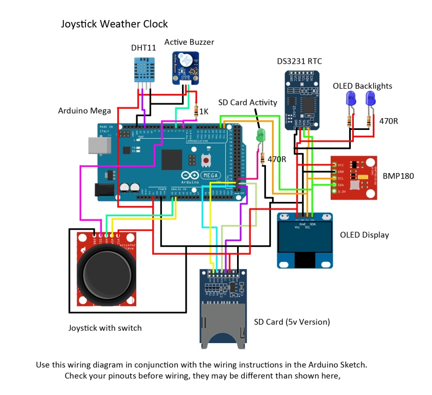
Use this wiring diagram in conjunction with the wiring instructions in the sketch. Different manufacturers may have different pinouts to those shown here, so check, The OLED will die instantly if connected incorrectly!
The two small blue LEDs sit under the OLED and give a cool blue glow.
The program:
Upload the joystick clock sketch, the sketch sends some debug data to the Serial Monitor (9600, CR/NL selected) if you want to watch this output start the Serial Monitor now. The clock takes a snapshot of the pressure and temperature each hour and saves the data in a string. At midnight this data is moved to a second string (yesterday), the contents of that string is moved to a third string (-48 hours).
The graph displays the current 24 hours data for both pressure and temperature and -24 hours and -48 hours display can be seen by clicking the joystick. Data for the recorded pressure and temperature is stored in memory so if the power is removed, or the Serial Monitor is started the data would be lost. However, the data and a backup file are stored on an SD Card. The hourly data is stored in a CSV file that can be opened in Excel. The sketch checks for the presence of an SD card on first starting. If one is found data will be stored on the card and any backup data will be uploaded.
If your RTC is already programmed with the correct time and date then the clock is up and running. If the time needs to be adjusted this can be done in one of two ways. Line 188 in the sketch is currently REM’d out (RTC.adjust(DateTime(__DATE__, __TIME__));) to set the clock un REM then upload the sketch. The RTC will be set to your computer time. REM line 188 again and upload this sketch (otherwise the RTC will be reset every time you run the sketch).
After a short Splash Screen the Home Screen is shown. This is an Analog Clock, the current Alarm state is shown and this can be set/unset by clicking the joystick switch. Move the joystick left or right to cycle through the various screens. Only one screen, the Alarm Set screen uses the Y (up/down) direction. To set the alarm, when the screen first opens the Minutes will be displayed with an underline. The minutes can be increased or decreased by moving the joystick up or down. Click the joystick to move the underline over to the hours, this can then be set as the minutes were set. When the correct time is displayed move the joystick back to display the analog or digital display and set the alarm by clicking the joystick.
The alarm uses an active buzzer, this is pulsed on and off about once a second and the time has been set to run for 10 seconds (although this can easily be changed. The on-board LED is also connected to the alarm code.
The event timer counts up from zero to 99 minutes. Start and stop by clicking the joystick switch.
The barometer has a number of functions, first the current pressure in millibars, or pascals is shown. This is compared with the last reading taken and the direction (rising, falling or constant) is shown. Just after the hourly reading this direction will almost always show constant, but as time passes this can show rapid changes in pressure between hourly readings.
The next barometer screen shows a graph of pressure readings taken each hour over a 24 hour period. The graph starts at midnight and continues until the last reading at 2300 hours. The data is stored in a string and just before the first reading at midnight the data is moved to a second string, the data from that having been moved to a third string. Data is therefore available for up to a three day period. To see an earlier 24 hour period click the joystick. The small ticks represent four hours. The bottom line is 990mb, the second line up is 1000mb. The next line up is 1010mb and the top line is 1020mb.
The last barometer screen is a Weather Forecast. This is the kind of forecast available on the old fashioned banjo barometers. The last two readings are compared, first to see if the pressure is rising or falling, then the rate of change measured. A forecast is then made based on these results. A result of this is that the forecast can be up to an hour old however, the forecast can often be good indication of weather conditions over the next hour or so. Clicking the joystick while this screen is showing will display the last forecast made and this can often give a better idea of the coming weather. A forecast cannot be made until the second hourly reading has been taken and the earlier forecast will not be available until three readings have been taken,
The next screen screen shows the current temperature in Centigrade, clicking the joystick displays the temperature in Fahrenheit. The temperature over a 24 hour period is shown on the next screen in the same way as the pressure screens. Click to display the last wo days data. The temperature is only displayed in Centigrade and the lower line represents 0C, the next line 10C, 20C and the top line 40C. If the temperature probe is to be placed outdoors the code would need to be altered if temperatures below zero are expected.
A moon Phase Screen is next, showing the phase of the moon in simple graphic format and the number of days to the next full moon. Clicking the joystick will show the name of the current months Full Moon. One of three version, Medieval English, North American Indian and Chinese names are shown, chosen at random.
There are two calendar screens, the first shows the month and day, rather like the old tear off calendar blocks, clicking on this shows the appropriate verse for today from the children’s rhyme Mondays Child. The second screen shows the month in standard calendar format and should be good for some years to come. Clicking on this screen will show the verse for the current month from the poem by Sara Coleridge.
About the joystick:
The joystick I am using has two potentiometers, X and Y, and a switch activated when the joystick is pushed down. With the connector on the left pushing the stick to the right moved from the analog clock to the digital clock. Pushing the stick up increased the values in the on the alarm set screen, for more information see this blog. The switch was very noisy so the code includes a ‘de-bounce’ routine. There is also a small delay in the joystick routines to ensure smooth switching of the screens. Move the joystick either fully left or right then allow it to return to its natural centre before moving it again. Occasionally the screen will skip to the next if the joystick is moved to quickly. The ‘centre’ value is read when the sketch first starts up to allow different units to be used without altering the code.
The Code:
The code consists of a number of routines controlled from the main loop, each screen is given a number and moving the joystick left or right will increase, or decrease, the current screen number. A switch loop is then used to call the required routine. The rest of the main loop checks the alarm time, gathers data each hour and sets or resets various variables and flags.
The use of an SD card is optional, if one is found then the buzzer is sounded twice, otherwise the buzzer only sounds once. The data is saved in CSV format to allow it to be read into a spreadsheet program. Data is saved once an hour as a backup. If this file is available when the program starts the buzzer will sound three times as this data is loaded. This is useful if there has been a temporary loss of power. Be aware that the data may be out of date if the Arduino has been powered down for some time.
Using delay() with U8glib can cause problems with screen refresh, so when a delay is needed (for example in switch de-bounce) the method used in the Arduino example for flashing a LED without using delay() was needed. Interrupt Service Routine is used to detect when the button is pressed and the ISR toggles flags that tell the routines to select alternative screens, or start and stop timers etc. The code is somewhat rambling. but achieves the aim I wanted. There is not much space left on the Mega and most of the diagnostic messages to the Serial Monitor have been REM’d out. There seems to be no problems with stack overflow .
In conclusion:
I had a lot of fun developing this project and intend to build a permanent version. I have extracted some of the routines and converted them to stand alone projects. My favourite routines are the pressure plotting routines and the weather forecast. I deliberately avoided using Progmem, but an optional an SD card can be used to store data.

Chris,
Hi – greetings from wet and miserable Germany.
I want to build this project so I have downloaded the code and added the various libraries but I get this error when I compile:
Arduino: 1.8.0 (Mac OS X), Board: “Arduino/Genuino Mega or Mega 2560, ATmega2560 (Mega 2560)”
/Users/AlanGP/Downloads/Arduino_Downloaded_Sketches/Arduino-Joystick-Weather-Clock-master/JoystickWeatherClock/JoystickWeatherClock.ino: In function ‘void childDay()’:
JoystickWeatherClock:1682: error: ‘class DateTime’ has no member named ‘dayOfWeek’
switch(now.dayOfWeek()){
^
JoystickWeatherClock:1719: error: ‘class DateTime’ has no member named ‘dayOfWeek’
if(now.dayOfWeek() == 0){
^
Multiple libraries were found for “SD.h”
Used: /Users/AlanGP/Documents/Arduino/libraries/SD
Not used: /Applications/Arduino 1.8.0.app/Contents/Java/libraries/SD
exit status 1
‘class DateTime’ has no member named ‘dayOfWeek’
This report would have more information with
“Show verbose output during compilation”
option enabled in File -> Preferences.
The verbose report is massive so I have not included it. It does show that all the other library elements have been picked up by the compiler.
I do indeed have multiple SD.h libraries but the compiler seems to work around that.
Could you please offer some advice on this issue.
Regards
Alan
LikeLike
Chris,
I think I am using a different ug8lib.h – easy to become confused with so much in the way of resources out there.
I will search your blog, I think I have seen a modified library somewhere.
Kind regards
Alan
LikeLike
OK I think I have resolved this but I wont be certain until I have uploaded and run.
In “RTCLib.h” there is a Class “DateTime” with a member ” dayOfTheWeek”. The sketch uses “dayOfWeek” which is causing a compiler error. I have changed the sketch to “dayOfTheWeek” in two places. The sketch now compiles but that doesn’t mean it will work 🙂
The sketch is too big for an Uno but compiles and uploads for the Mega without warning. Tried this on a Due but there were all manner of compilation errors associated with RTCLib – will check this out later
Regards
Alan
LikeLike
Alan, let me know how you get on. I recently posted an update blog, showing the project running after 15 months. Apart from the fact that the clock had gained 45 minutes all the rest was working perfectly. I will check the code I uploaded at the time just in case I did make some alterations but I don’t think I did. The code only just fits on a mega, with some space free for variables.
LikeLike
Just in case you are still having problems I have posted all the libraries I used for this project on my github page for this project. If you do install these libraries and have another version rename your original as, for example, RTClib_old.
LikeLike
Chris, Many Thanks – if I get around to the Due I will post the results.
LikeLike
Hi Chris,
Got the Joystick Weather Clock working, it’s a really cool device and definitely worth the investment and effort – thank you – the instructions were easy to follow. Its on a Mega, since I have yet to resolve the compilation errors that appear for the Due. The only reason for thinking about a Due is the available space and speed – the Mega works fine. A Due would provide space for the addition of a humidity sensor – I have a good friend who has just installed a small (cheap and therefore plywood) pool table in his cellar and this would make a good present because as I said this is a really cool project.
My plan is to make it permanent; I have a minimal 3D printed housing for the Mega (just to prevent shorts really) and I will use a Mega prototype board on top to mount the components and sensor boards.
I have it in mind to build a small UPS into it using a single LI-ION cell and a small charger/protection board – the output would go to a small boost regulator to produce 5v. Since prototype board are stackable, this can be an add-on and sit under the main component prototype board.
Firstly, I need to change the RTC for a DS3231 (I have a few) to increase the accuracy issue you found at the 15 months point. I first need to analyse the differences between the DS1307 and the DS3231. Obviously the define will change but I dont know what else.
I’m taking photographs as I go so, if all goes well and I have the time and you don’t have an objection, I might create an Instructable out of the project. I have no idea how to do that so it’s another challenge.
Is there any way of adding photographs to these comments?
Kind Regards
Alan
LikeLike
Alan, I am glad you enjoyed the project, it is certainly one of my favourites. I assume you have found all the various screens. I have replaced the DS1307 with a Ds3231 and it is a direct replacement. No changes to the clock library or code, all I had to do was swap the wiring on the socket for SDA and SCL. I understand that all DS1307 clocks drift by a varying amount, but that for a particular clock the drift is constant. This means you could use software to correct the drift.
I was going to add a humidity sensor, but there was no real memory left for one more display screen! I wanted to make sure that there was enough memory for the variables and the fact that it still performs perfectly almost eighteen months later shows that I must have erred on the right side. I suppose I could lose one of the less useful screens but I am reluctant to do that.
As for photographs, if you email them to me I will add them to the Blog, attributed to you. I took numerous photographs of my build with the intention of doing an Instructable, but never got round to it. Let me know how you get on and if you do write one I will link to it on this page. Chris
LikeLike
I have started the Instructable planning, it shouldn’t be too difficult because the editor is very good. However, it takes a lot of effort and planning to make a good Instructable so it will be some time before it appears. I will add the DS3231 to the Instructable and give you access to it before it gets published. I’ve also got an SPI version of the 0.96 OLED, which I would like to try. I think a humidity sensor would be a useful addition so firing up the Due would provide the extra resources needed. When you added the DS3231, did you change the #define or just plug and play?
LikeLike
Substituting the DS3231 is just plug and play, it needs no changes to either the library or sketch.
LikeLike
Alan, I have just added a Humidity Sensor (DHT11) and added another screen to be able to view it. I have uploaded the new sketch to github as well as adding the DHT11 library I used to the Libraries zip file. I hope to update the blog tomorrow if I can find the time.
Memory limitations mean that there is no variable space left to be able to save the data onto the SD Card, but the Humidity screen shows the DEW POINT as a bonus. Chris
LikeLike
Unfortunately, didn’t seem to work on my clock – I’ll check it out after work
LikeLike
I may have uploaded any earlier version that had a small error. The DHT11 OUT pin should connect to Arduino pin 12, not pin 2!
LikeLike
We’ve crossed over posts here – the DS3231 didn’t plug and play. I haven’t had time to investigate 🙂
LikeLike
Alan, Sorry about that. I am using a ChronoDot DS3231 board. On my DS1307 the four pins I used were in the order 5v, Gnd, SDA, SCL. on the Chronodot the SDA and SCL pins were reversed so I simply reversed the connections on my protoboard. Its working fine with no changes to the library or code. I have also uploaded a final version to GitHub today with the DHT11 added and some minor changes to the sketch.
LikeLike
Chris, thank you for adding the humidity sensor – it’s the icing on the cake as far as I am concerned. Thanks also for the mention, which was not necessary.
I still can’t get the DS3231 to plug and play, having now tried two separate but identical boards,the time is displayed accurately on the initial screen but switching between screens seems to lock up after some seconds. Re-inserting the DS1307 fixes the problem. I’m rushing around at present, which can lead to cock-ups, so I will spend some quality time on it this weekend and sort it out.
If not the DS1307 could stay – the primary function of this specific logger will be to check out the variations in temperature and humidity in the area of my friend’s pool table so an exact time reference is not absolutely essential. Obviously I’m not giving up on it – half of the fun for me is getting stuff working and, for the proposed Instructable to be credible, its all got to work as the project author (you) intended.
LikeLike
Alan, the only sugestion I can offer is to use the Library I used, its in the folder of libraries in the zip file on GitHub. I seem to remember you having to change the code to get it to work.
LikeLike
That could be it!
LikeLike
If you do swap libraries you will have to change the code you altered. I am watching the low pressure come over at the moment. 24hrs ago it was 1010mb, its now 999 and falling.
LikeLike
I’d worked that one out 🙂 I’ll be using your new code with the DHT11 in it. My Baro has fallen – I initially thought it was an error caused by my RTC swap but no -998 and falling. We are about 500Km apart so, when there is prevailing SW weather, we pick up your weather 12-36 hours later – modified by 350Km of main land Europe land mass. I’m at roughly 54deg46N by 8deg48E and 140m above mean sea level.
LikeLike
Hi Chris,
New code loaded and libraries installed, I found that I needed to change RTCLib, I2CDev and BMP085 from my defaults before it would compile . Still won’t run with a DS3231 – exactly the same as before. I don’t have a DHT11 so I used a DHT22 and the programme can’t find it. I tested all my DHT22 modules using the (standard DHT.h library) examples and they all work fine and my wiring is OK.
I’ve ordered a DHT11 from a local vendor (Euros2.99) just in case, be here on Saturday, but it might be that I need to use all of the supplied libraries instead of just seeing what causes a compile fail.
In some ways it’s better that it didn’t work out of the box, so to speak, I am learning a lot more this way. This is an intriguing situation, which – initial frustration aside – makes it all the more interesting and I have yet to try all the options.
Regards
Alan
LikeLike
Alan, sometimes the Arduino can be frustrating. When I first started using it there were only a few libraries, now you can often find several, all working slightly differently. What I have learnt from this experience is that in future I will package the libraries with the project on GitHub. Can I ask what version of the IDE you are using,also if you installed the libraries I used did you either delete your versions or move them out of the library folder to a safe location?
LikeLike
I’m on Arduino 1.8.0 and I renamed the libraries “name_old” before I dropped your libraries into my sketch folder. I don’t get any compilation errors and there was one occasion today when the DS3231 actually worked as intended but faulted again after a reset. I removed the I2C pull-ups (SDA and SCL) from the DS3231 RTC as there seem to be pull-ups on most of the modules I’m using but not the DS1307 RTC. One step closer. The DH11 should be here tomorrow – well later today actually 😄
LikeLike
Alan, if you have the buzzer connected, at powerup you should hear a beep, a slight pause then three beeps. This shows the RTC, BMP180 and DHT11 are all working. You can also check whats working by watching the Serial Monitor at powerup (apologies if you have already found that). Good luck with the DHT11 and by the way I am using 1,65 IDE, I installed 1.8 after I asked which version you were using but I cant get to try it until Monday. I just wondered if 1.8 was having problems with any of the libraries. One other thing I can suggest is to leave the hardware set up but check each module by just running an example sketch for one sensor. If it works OK like that but not when you run the weather clock sketch then there is a problem with the weather clock sketch. If it will not run correctly then there could be a wiring problem. The low pressure looks to have passed us now so by tonight you may have our clear bright weather.
LikeLike
Chris,
Funny old thing that’s exactly my plan. I’m going to make up a special harness with crimp connectors to get all the I2C modules off the breadboard ( I have a number of other projects planned using I2C modules so it’s not a waste), which will prove the wiring but I’m already fairly happy that it is OK – the harness will get rid of about 20 joints on the breadboard, which could be resistive or just plain bad.
I’ve already tested the DHT22 in another sketch and also the DS1307 and DS3231, with just the baro remaining. The DHT11 didn’t arrive today so should be here Monday and I will test it before putting it into the clock. The serial monitor indicates that all is working except that the humidity board is missing just the same as the indication on the OLED and the buzzer give one longer beep and then two short ones on reset or power on. With the previous version I got 3 short beeps. I’ve recovered about 5 days worth of data from the SD card so that works to plan. The SD card unit is SPI and has the level shifters on board and is a proven piece of kit.
It all compiles once the RTCLib, I2Cdev and BMP085 libraries are substituted, I’ve yet to use the rest and I would be interested to know which of the libraries you actually optimised for this project? I’ll get there eventually, if the sketch works for you it should work for me as long as I can more or less duplicate your hardware and software. My DS3231s are generic and I notice yours is the Adafruit module – I’ll even get one of those if I have to but I already have about 10 of the others 😄
Regards
Alan
LikeLike
Alan, I used a ChronoDot from China at less than £3, funny thing was that a UK company I tried to buy one from, at twice the price, would not deliver to the Isle of Wight. The Chinese Company did post free! I chose the ChronoDot because of its size and it fitted into the space left by the DS1307 perfectly.
If you recorded data over 5 days then the clock must have been working as the save to SD is triggered by the clock. Was it with the DS3231?
Regards
Chris
LikeLike
Alan, you are not using the SPI version OLED are you?
LikeLike
Hi Chris,
I’m using the I2C OLED and I am using the project libraries.
The data collected was with the DS1307 in circuit.
The original project with the original components works fine but the original project with the DS3231 fitted doesn’t work for me. The V2 project with a DS1307 and a DHT22 works except that the humidity sensor is not detected.
The V2 project doesn’t work for me with a DS3231 fitted – back to the DS1307.
I have just fitted a new DHT11 having tested it with the example sketches and the V2 software still gives me the same fault – the humidity sensor is not detected.
I have tested the circuit with other sketches for the individual I2C modules and the DHT11 and DHT22 and they all work – with the standard libraries.
I have changed the Arduino Mega – same result.
I have completely rebuilt the project from the ground up twice – no change.
I have decoupled the power at every module – no change.
I have used external power for the modules – no change.
I have logic analysed the I2C bus and been all over the project with an oscilloscope.
I am at a loss and rapidly running out of options.
However, I am wondering about the DHT11.h library.
There are standard DHT libraries available
Regards
Alan
LikeLike
Alan do you mind if I email you directly rather than try to communicate via these comments?
LikeLike
Sure – that would be fine.
LikeLike
Alan, did you get my email? Chris
LikeLike